Index |
Last Chapter |
Next Chapter |
Computer modelling techniques and, to a lesser extent, image processing techniques, are used widely throughout this thesis. In order to make the material introduced in later chapters more familiar, a brief qualitative introduction to the basics of image processing and computer modelling is given in this chapter.
Image processing is primarily a set of techniques to make images more meaningful to humans, as opposed to computers (many computer techniques work best with the original, unaltered images). Image processing works by removing features of an image that confuse the human eye, and enhancing other features that make the underlying structure of the image recognisable. This is often performed by attempting to understand the physical process that caused the imperfections in the image and then, by mathematically reversing their effect, returning to a closer approximation of the 'ideal', defect-free image. Image processing is now a standard procedure in high-resolution optical microscopy.
Computer modelling attempts to imitate on a computer a real world object or process, by using mathematical equations and rule-of-thumb heuristics. This is usually done in order to investigate a real world system in a cost effective way: it is cheaper to make a model of a bridge, and test assumptions about weight and loads on its component girders, than to build the bridge and experiment on the real object.
Image processing has become a common technique for making images more comprehensible to the human eye. In recent years image processing techniques have become so commonly used that they are now routinely built into common everyday appliances. Scanners and fax machines regularly do contrast and brightness enhancement and balancing, and many digital cameras and video cameras use techniques such as Fourier transformation (1) in order to automatically obtain focal lengths.
It is important to note, however, that image processing cannot add anything to a picture that was not there already. Popular cinema aside, it is not possible to take, say, a satellite photograph with a resolution of 10 centimetres, and image process it to reveal the details on a car licence plate. If the information does not exist in some form in the image, no amount of image processing can produce it. There is also a danger with some image processing techniques that artefacts will be introduced that did not exist in the original, by overemphasising random variations in the original image.
The following sections outline a number of the more common techniques that are used later in this thesis.
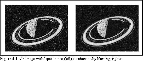
This is the computational equivalent of physically spreading Vaseline on a camera lens before taking a photograph (a technique actually used by cameramen in the past). It blurs the image slightly, allowing colour from one location to seep into the surrounding locations.
This has a number of uses. First, if an image is degraded, smoothing may result in an image more meaningful to human eyes. An example might be a particularly grainy photograph that, when blurred, may appear more natural. Another example is a picture with scattered point-like defects in it (see Fig. 4.1) - smoothing the image may make such defects less apparent.
Second, if an image is obtained via some digital technique such as a fax or scanner, it is possible that the image has been artificially sharpened - that is, that the edges of objects in the image have in some way been intensified. Smoothing, which leaves large regions of the same colour and intensity unchanged, but smears edges, may restore an image's original appearance.
The danger with image smoothing is that it may blur lines and borders, and that it will destroy the fine detail of a picture. The same process that prevents us from seeing the wrinkles in an actor's skin may prevent us from seeing the fine structure of an organelle under an electron microscope, if we use image smoothing to try to improve our image.
The converse of image smoothing is image sharpening, which deliberately intensifies the edges of objects (Fig. 4.2). While there are not many physical analogues of this process, it is actually similar to what the human optical system does. The eye, in combination with the various visual portions of the nervous system, acts to emphasise lines and borders, at the expense of broad regions of colour - an adaptation that allows swift recognition of the outline of an object.
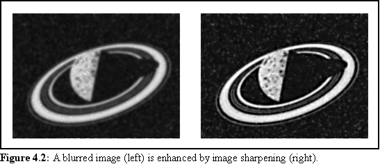
The difficulty with image sharpening lies in its sensitivity to changes in shade. Whereas it can easily emphasise a boundary between two slightly different shades of grey, it will also emphasise boundaries between an isolated dark or bright dot - thus if there is any noise in an image, image sharpening will increase it, possibly making the image useless.
Histogram equalisation is used to process images that are lacking in contrast. The lack of contrast may be in all shades (when an image is under- or over-exposed), or may be due to certain shades 'bunching up'. The latter occurs when the image is correctly exposed, but the objects photographed have insufficient contrast between each other. An example of this might be a photograph of a herd of similarly coloured grey elephants - the photograph may be perfectly exposed, but it is difficult to distinguish individual elephants due to their similar shades of grey.
In some ways histogram equalisation is similar to what happens when a skilled developer processes a negative. With the proper use of photographic paper, an under- or over-exposed image may have its contrast improved so that the image appears normal. For example, the intensity range of a heavily under-exposed image, (that would normally appear to be black and shades of dark grey), may be 'stretched' so that while the black stays black, the lightest of the dark greys becomes white. All the intermediate shades of dark grey are interpolated between white and black, but all become lighter than before.
A computer can also perform this task, but with slightly more control over the final shading. Since a computer image has only a finite number of elements, or pixels, and a finite number of shades of grey, we can tabulate the number of pixels represented with each shade of grey into a histogram (i.e. a frequency count). Using this histogram the computer can assign each pixel for a given shade of grey to a new value, possibly producing a more informative picture.
Histogram equalisation is the process whereby the computer attempts to redistribute the shades of the picture to produce a more easily interpreted image. One way of doing this is to ensure that the picture has equal quantities of all the different shades from white to black. There are other results one can obtain using a histogram, such as determining a set of shadings that are distributed normally around the mean shade. This can lead to more 'natural'-looking photographs.
The method used in figure 4.3 is yet another approach, where the image is 'stretched', so that the lightest shade (which in the example is still very dark) becomes white, and all the other shades are mapped linearly to intermediate values.
The example below (Fig. 4.3) demonstrates the use of histograms. The original image is shown in the top left-hand corner. In the top right-hand corner is the same image, darkened considerably (note that this darkening has caused some loss of information - it is not possible to completely recover the original image from the dark image).
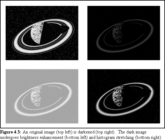
There is still considerable room for improvement of this very dark image, however. Simply brightening the image provides some improvement, as can be seen in the image on the bottom left, though it still looks very washed out and gray. On the other hand, histogram equalisation, shown bottom right, that has stretched dark greys to light grey and white, while leaving pure black unchanged. This recovers most of the original contrast. This technique is often used to improve badly exposed photographs, and indeed is often done in hardware by modern digital cameras.
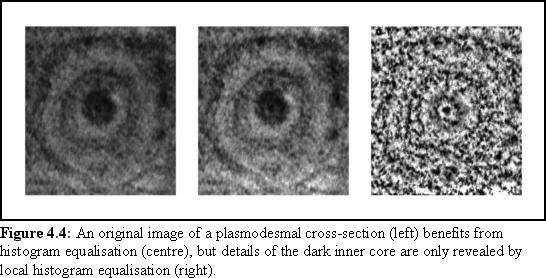
A more elaborate use of histogram techniques is to apply the same principle on a regional basis to an image. This allows detail to be extracted from regions that are unusually lacking in contrast within a larger image that may be perfectly well adjusted otherwise. For example, in a picture of a dark cave entrance taken on a bright sunny day, the cave entrance may appear entirely featureless, but localised histogram equalisation may be used to reveal the black bear lurking within.
There are a number of ways that localised histograms can be used. A naive approach is simply to divide an image into subsections, and individually process each subsection as if it were an entire image. The shortcoming of this approach is revealed when an interesting region straddles the intersection of multiple subregions.
A better approach (implemented by the author as part of the work described in chapter 10) is to construct a histogram of the region surrounding each pixel in the image (Fig. 4.4). (Although this might seem labourious it is possible to keep a running total of the histogram as the focus of the algorithm moves from pixel to pixel.) Using this method, each pixel is guaranteed to be adjusted appropriately to its surroundings. Of course, the exact size of the surrounding area that should be taken into account is a configurable parameter.
Another set of common image processing techniques use Fourier transforms. A Fourier transform models a particular shape as a series of overlapping sine waves of different frequencies - a process that is a little counterintuitive, but nonetheless very powerful. Fourier transforms can be applied in two dimensions, the image being transformed into a two-dimensional grid of the different frequency waveforms, or components, underlying the image. The Fourier transform takes a normal image of pixels, such as a scanned photograph, and converts it into an image in 'frequency space'. Since no information is lost during the process, the resultant Fourier transform of frequency components can be represented as another image of the same size as the original, usually having the appearance of a black image with a regular pattern of gray dots.
The upshot of this is that features of the image that show regular periodicity throughout the entire image can be manipulated - for example, artefacts such as regular scan lines can be removed from an image by removing the appropriate frequencies in the 'frequency space', or Fourier transform image.
An image can also be 'smoothed', and high-frequency noise (i.e. isolated spots and lines) in the image can be removed by eliminating all the high-frequency components of the Fourier transform image. Conversely, small features such as edges and points can be enhanced by removing all the low-frequency components of the Fourier transform image. This exclusion of a set of frequencies in the Fourier transform is called 'bandpass' filtering (since a range, or band, of frequencies is included/excluded).
In fact Fourier transforms were not widely used in this thesis, but a short investigation of angular periodicity was made using a variant of the Fourier transform, the polar Fourier transform.
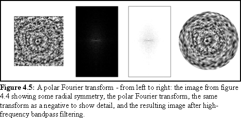
A variant of the Fourier transform is the polar Fourier transform. A normal Fourier transform breaks up an image into a set of Cartesian frequencies, that is the frequency components are arrayed on the x and y axis. But it is also possible to represent an image in polar co-ordinates (i.e. angle and radius) and then use a Fourier transform to find the frequency components in the angular and radial directions.
The advantage of this is that it makes it possible to emphasise features with radial symmetry (i.e. concentric rings) and angular symmetry (such as the spokes on a wheel) by bandpass filtering. If the image is noisy, removing the high-frequency components will reveal any underlying radial or angular regularities, while conversely removing low-frequency components will emphasise the edge features of any such angular or radial features.
This technique is used briefly in chapter 10 to examine the angular symmetry of a biological specimen. The example below (Fig. 4.5) shows the same example of a polar Fourier transform.
The most obvious limitation of image processing, as mentioned in the introduction, is that it cannot reveal details that are not in some way present in the original picture. Further difficulties occur if the techniques are misused - if images are over-processed it is possible to produce artefacts that are not present in the original image, by amplifying random noise until it becomes a feature of the image.
For these reasons it is important to always have the original image available when viewing the results of image processing, so as to be able to compare the image-processed result with its base image.
Modelling is a broad term covering any abstract representation of a physical object or process. The term 'model' is sometimes reserved for static representations, while 'simulation' is used for representations of dynamic processes, but the difference is largely arbitrary, and the two terms are used interchangeably within this thesis.
Modelling has been used since ancient times as a precursor to construction, and this use continues today. Modelling of the sort needed for modern engineering requires consideration of a great many physical parameters, such as gravity, material properties and wind loading. A mathematical abstraction is constructed of the object, and mathematical terms representing the various physical systems that act on or comprise the object are introduced into the system of equations.
The modelling performed in this thesis is of a similar type - physical objects at the nanometre scale are modelled as a system of equations, and the various physical forces acting on them are introduced as terms in these equations. Due to the complexity of the problem, these various equations are broken up into separate computer algorithms and solved numerically, rather than analytically.
Under some circumstances, the mathematical equations underlying the model of a particular system may be amenable to a theoretically exact, analytical solution. An example of this is a simple model of the ballistic flight of a ball, where the equations of motion can be expressed mathematically, as y=� gt2 + vyt and x=vxt (where 'g' is gravity, 't' is time, and vy and vx are the initial velocities in the vertical and horizontal directions respectively). These equations yield exact solutions for all values of 't'.
Unfortunately many real-world situations cannot be modelled accurately with analytic techniques, because the equations involved are too complex to yield exact solutions. If the above example of a ball in flight was to include consideration of air resistance, turbulent airflow, wind gusts, and gravitational variation, it would probably not be susceptible to an analytic solution.
It is usually possible, however, to obtain approximate answers of arbitrary accuracy using numerical techniques. In these techniques, a 'guess' at a solution is made and inserted into the system of equations. The guess is then modified by small amounts until a solution of acceptable accuracy is derived.
Before the introduction of computers these types of calculations, which were common in many branches of engineering, were labouriously performed either by pen and paper, or using slide rules (5), (6). With the introduction of computers, such calculations can be performed far more swiftly, accurately and reliably in an automated fashion.
A related form of modelling is that of graphical modelling, where complex shapes are represented (again mathematically) by the computer, and used to produce visual representations that are presented to the user (who is usually able to view the simulated object in a number of ways). That each such view of the mathematically modelled objects requires a host of numerical solutions to various 3-D viewing equations is of no consequence to the user, since such calculations can be performed rapidly, in real-time, on a modern computer. The visualisation of the state of simulated protein assembly processes in this thesis is done in this way.
Another way of classifying models, independently of whether they are analytically or numerically solved, is whether the model describes a process that is changing over time, or is static. Much modelling is done using static representations. Structures such as houses and bridges that are presumed to be immobile are modelled using static models, or indeed the original DNA model by Watson and Crick (7). This thesis uses static models to describe theorised biological structures in chapter 10.
Other objects, which change over time, are represented by dynamic models. Such models are often more complex than static models, because they may have to model all the features required of a static model, and repeat these calculations frequently as time progresses (e.g. it is easier to model a stable house than the same house sliding down a slope during an earthquake).
A common approach to dynamic modelling is to break the simulation into a number of discrete instants. This is a type of numerical approximation in which a static model is constructed for a particular instant, and the forces acting on every relevant part of the model are obtained. It is then calculated how far all these objects will move during a short 'time step', when the calculations are repeated using the new object positions. This approach, like most numerical methods, can be made arbitrarily precise by choosing smaller and smaller time steps. The nanoscale simulator described in this thesis works using time steps the length of which can be set as a program parameter at run time.
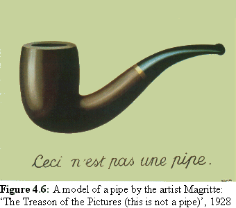
The fundamental problem of all modelling is that no matter how elaborate the model, it can never approach the complexity of the real world physics underlying the modelled object, with all its component molecules and atoms, and all the external real-world objects that act upon it. This is sometimes expressed by the colloquial phrase 'the map is not the territory', or as the famous picture by Magritte (Fig. 4.6), which is indeed not a pipe, but rather a picture of a pipe. In order to do any meaningful modelling it is necessary to radically reduce the real-world situation to a manageable size.
Similarly most complex modelling requires even the mathematics of the simplified model to be approximated, and the degree to which this approximation is done must be selected with care. Almost always (and certainly in this thesis) there are trade-offs to be made between accuracy, speed, the usability of the resulting data, and how closely the mathematical model approaches the physical reality being modelled.
Despite these limitations, modelling has been an extraordinarily successful method of understanding the world, and models with known limitations (e.g. the Newtonian theory of gravitation) are used to great effect by scientists and engineers every day.
With the exception of figure 4.6, all the exemplar images in this chapter were created by the author using "Paint Shop Pro 5.0" by Jasc Software Pty. Ltd., (for the non-Fourier transform image processing examples), or the "Image Explorer" suite of image manipulation tools supplied by SGI for the Fourier Transform example. The raw image of the ringed planet was created by the author using the freeware 'Povray' raytracer program, while the cross-sectional TEM of a plasmodesma was provided courtesy of Janine Radford, Dept. Biological Sciences Monash University, Melbourne, Victoria, Australia.
Index |
Last Chapter |
Next Chapter |
1. James, J.F., (1995) A student's guide to Fourier transforms with applications in physics and engineering, Cambridge University Press, Cambridge
2. The material presented here is relatively complex, (i.e. it would be covered in an undergraduate mathematics course), and space does not permit a full exposition of Fourier transforms. The reader is directed to a good mathematics text, such as Kreyszig, E, Advanced Engineering Mathematics, (1983), John Wiley & Sons, Inc., New York.
3. All good Physics and Engineering texts that cover mathematical solutions to problems are implicitly analytical modelling texts: e.g. Kreyszig op cit.
4. A large number of textbooks on numerical techniques are available, e.g. Smith, G.D., Numerical Solution of Partial Differential Equations: Finite Difference Methods (3rd Ed.), (1985), Oxford University Press, Oxford.
5. An intriguing description of the process of mass slide rule calculation can be found in the description of airship manufacture, in Nevil Shute's autobiography: Shute, N., Slide Rule, (1956), William Heinemann Ltd., London, Chapter 3
6. The author's grandfather, Mr H.C.V.Woollard, also described how competing teams of slide rule operators worked to calculate the mesh modeling the weakest cross-section of double-curvature dams in the Tasmanian Hydro-Electric Commission in the 1950s. The use of multiple teams was an important error checking mechanism.
7. Watson, J. D. (1968), The Double Helix, Penguin Books Ltd., Ringwood, Victoria, Australia.