
Index |
Last Chapter |
Next Chapter |
Et e fistulis fit robur
Strength also comes from tubes.
- anon
Tubulin is another common cytoskeletal protein that has also been studied in great detail (2) (see Chapter 2). It forms long tubes that are common in almost all eukaryotic cells, and has a role in cellular transport. It plays an essential, if not fully understood, role in cell division.
Part of the work described in this chapter was presented at the 1997 Molecular Biophysics of the Cytoskeleton conference held at the University of Alberta in Banff, Canada (3).
Tubulin comes in two very similar varieties, -tubulin and -tubulin, which are usually found bound together to form a tubulin dimer, which is the usual form that polymerises to form microtubules (a third, more stable type '-tubulin' is found in cells, but is less abundant and has not often been used in-vitro). The tubulin dimer is the fundamental building block, and how the protein is generally found under normal physiological conditions.
Free tubulin dimers can self assemble, and exhibit the same general behaviour as actin. Microtubules (sometimes abbreviated as mt-s) can self-assemble from free tubulin dimers in-vitro, and both dimers and polymers exhibit in broad terms the same general behaviour as actin monomers and polymers. Both assembly and disassembly occurs at a faster rate at one end, called the "plus" end, than at the other, the "minus" end (Fig. 8.1). As with to actin, tubulin dimers come in a high-energy form that favours binding, and a low-energy form that favours disassociation. Unlike actin however, tubulin uses guanosine 5' triphosphate, GTP, rather than adenosine 5' triphosphate, ATP, as its energising molecule (though the two are very similar). While the GTP binding site on -tubulin forms part of its permanent bond with a corresponding -tubulin monomer, the GTP binding site on -tubulin can be hydrolysed to GDP (the 'diphosphate' form), causing -tubulin, and in fact the whole dimer, to become less strongly bound, and more inclined to break away from the microtubule aggregate. Thus, when a dimer is said to be a "GTP-dimer" or a "GDP-dimer", in fact it is the state of the -tubulin monomer that is being directly specified, although this state affects the entire dimer.
Another difference from actin is that the low energy GDP-tubulin form, when free, does not appear to bind at all to a growing microtubule, while free ADP-actin will bind to a growing actin filament, albeit more slowly (see Fig. 8.1 (4)).

The structure of microtubules is more complex than that of actin filaments, being a hollow tube, and as a result the processes of assembly and disassembly are not well understood. The standard theory (5) is that a cap of GTP-dimers forms on the growth end of the microtubule, and that if this cap is lost (due to physical loss of the GTP-dimers, or due to dephosphorylation) the microtubule will switch from growth to very rapid disassembly (6). Under some circumstance whole microtubule populations may switch from growth to dissassembly and back again, in a process known as microtubule oscillations, which can be mathematically modelled (7).
 The structure of microtubules has been extensively studied using
electron microscopy and image analysis, and by observations of
their growth under unusual chemical conditions. For example,
tubulin can be made to polymerise into sheets or rings by altering
the growth environment in-vitro using different concentrations of
zinc and calcium, and various tubulin affecting drugs such as
vinblastine and taxol.
Microtubules come in a variety of structures, the most common of which under normal conditions is a 5-start, period 13 helical tube of dimers (8), which can be visualised as being made up of 13 offset strands, or "proto-filaments" longitudinally (Fig. 8.2 (9)).
However, the tubulin polymerisation curves derived from experiments are not well described by this type of model (10), due to the difficulty of determining the nucleation process, and the size of the "critical nucleus" (the minimum polymer size at which growth is more probable than disassembly) (11). They are better described analytically using a two-stage nucleation model (12), or with even greater accuracy using a multi-stage nucleation model (13).
Microtubule self-assembly is more complex than that of actin. This makes it a more interesting problem to study, as well as presenting more difficulties in determining an accurate model. Since the size, stability and nature of the "GTP-cap" is not known precisely, a given simulation must make assumptions, and choose a particular capping model. Again, this makes for a more interesting area of study, as different cap models can be trialed in the simulator. The trade-off is that the accuracy of each model cannot be easily gauged as the correct model is not known.
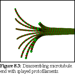
A complication arises due to the change in structure of disassembling microtubule ends. These are observed to break up into a hydra-like spray of individual protofilaments (Fig. 8.3): While there has been some dispute as to how much of this is due to experimental conditions, and how much is intrinsic to microtubule disassembly (14), it seems likely that this does play some role in the rapid disassembly observed in microtubules.
Since microtubule structure may play a role in both assembly and disassembly, the shape and nature of the ends of the microtubule may effect the rates of assembly and disassembly, and also the possibility of rescue (15) (i.e. the splayed shape of the disassembling microtubule shown in figure 8.3 may make it more difficult for it to recover into a stable growth tip.) This presents a challenge to the simulator. While the program architecture and the .pddf modelling language both allow for conformational change modelling of the type required to model the hypothesized changes to end structure, this is not currently supported by the nanosimulator program. Due to this limitation, it is not possible to model those theories that involve structural change with the current version of the simulator. In addition, it is not currently possible to model the flexibility/elasticity observed in bending microtubules (16), or in the splayed disassembling tips (17).
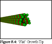
Another issue is the structure of growing ends, with recent research indicating the probable growth structure as an extending curved sheet, that closes up into a tube (Fig. 8.5,8.6), rather than a simple 'flat' ended top (Fig. 8.4):
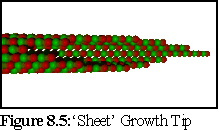
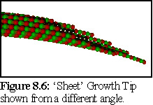
Experimental observation of fast-frozen growth tips also indicates that there is a force resisting the curling of the microtubule tip into a tube, which leads to the growth tip being splayed into a flatter shape than would be indicated by the curvature of the closed microtubule (18). (Nb this flattening is not fully represented in Fig. 8.5 & 8.6)
The simulator is able to model the structure of the bonds, but not (currently) the changes in inter-dimer angles that initially create the flattened sheet, and later cause the sheet to close up. However, while these structural changes are doubtless important in microtubule formation, the mathematical model of the simulator is unlikely to be strongly affected, since it deals with dimers on an individual basis.
Experimental studies of tubulin have provided accurate details of the assembly and disassembly rates of the growing microtubule ends. To test the simulation, an arbitrary in vitro environment is chosen for which good experimental evidence is available. The current simulation uses data from Walker et al (19), who used a standard experimental environment conducive to microtubule growth, at 37C, and obtained the following figures (Table 8.1, also used in Fig. 8.1):
| GTP-Tubulin | GDP-Tubulin (hypothesised) | |||
| + end | - end | + end | - end | |
| kon (M-1s-1) | 8.9 | 4.3 | 0 | 0 |
| koff (s-1) | 44 | 23 | 733 | 915 |
Table 8.1 Tubulin association and disassociation rates (20)
There are some important differences between the tubulin data in Table 8.1 the equivalent actin data (Table 7.1).
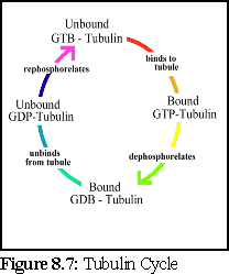
Using these figures, a .pddf file is constructed, that uses a four-state model for tubulin; unbound and phosphorylated, bound and phosphorylated, bound and dephosphorylated, and unbound and dephosphorylated. This represents the presumed cycle of binding, dephosphorylation, unbinding, and rephosphorylation (Fig. 8.7).
Rephosphorylation requires an energy input into the system, and can occur when free unbound GTP replaces the phosphorus-depleted GDP of a free tubulin protein. This occurs within the cell, and can be simulated in vitro simply by providing free molecules of unattached GTP.
A simple model of the dimer is used, where the dimer is represented as two permanently attached 2nm radius spheres, giving the unit dimensions of 8nm by 4nm by 4nm. This is close to, but not the same as, recent measurements of tubulin dimers as being 46 x 80 x 65 Å (24).
The model used assumes five possible states for tubulin:
The model used is the simple cap model, where GTP-tubulin is hydrolyzed to GDP-tubulin after the 'top' link (i.e. the axial -tubulin link) is bound (25). In order to simulate the extra instability that occurs in this model when GDP-tubulin is exposed at the '+' end of the microtubule, two GDP-tubulin states are used, a stable and an unstable form.
The events which change the state of the dimer are:
Using the experimental figures of table 8.1 in the simulator requires some further computation. To set up the .pddf files, we need to have binding and breaking values on an individual protein basis. The problem is more complex than with actin, since it is impossible to ignore the multiply bound state of tubulin dimers, and the dimers have four or even six possible binding sites rather than two, since they can bind at the sides as well as forward and back.
For the sake of simplicity, the geometrically simplest (and the most common) species of microtubule is used in this simulation, being the seamless 13 protofilament microtubule (26).
A further difficulty lies in the uncertain structure of the microtubule ends. Since some dimers are likely to be held more tightly than others, and it is unclear exactly how many dimers at the ends will be held by one, two, or three bonds, it is difficult to calculate a priori the individual dimer link breakage probabilities. For the same reason, while any of the protofilament ends can theoretically bind free dimers, obviously the more exposed monomers will be more likely to bind than those with only one available link, or those that are partially blocked by their neighbours.
Another important point to note is that it is not possible to distinguish, on the basis of the experimental evidence available, differences in binding rates depending on the state of the tubulin protein already bound at the tip of the microtubule (whether phosphorylated or not). Although it might be suspected that such differences exist (and if they do, they can be modelled using the simulator), this particular .pddf model does not explicitly include them.
Due to these difficulties, a number of different models based on the figures in Table 8.1 were trialed in the simulator. The method used was to estimate the dimer probabilities with the aid of the following equations:
p(binding) = p(top collision)*p(top bind)+p(bottom collision)*p(bottom bind)
+ p(left collision)*p(left bind) + p(right collision)*p(right bind) (8.1)
This equation describes the probability, per dimer, of binding another dimer in terms of the probability of various types of collision (side, +end, -end), and the probability of binding given such a collision.
To estimate breakage rates more assumptions must be made about the state of the microtubule ends. The total off rate will be determined by the number of dimers available to break and the number of bonds to be broken. Using the "order of magnitude" breakage heuristic described below, the probabilities for a dimer breaking away is that of the strongest bond (side, +end or -end) divided by 10 for every link beyond the first.
For example, if the "sheet growth tip" model is employed, it is assumed that on average one dimer will be singly bound, eleven doubly bound, and one triply bound (e.g. the tip in Fig. 8.5). With the further assumption that the bond strength is the same for side and +end bonds (this is a large assumption) then, using the multiple link breakage model described below, the per-link breakage rate could be found from:
p(dimer breakage/microtubule) = p(single bond breakage) * (1+11/10+1/100)
= p(single bond breakage) * 2.11
(8.2)
Since the total off rate for the microtubule is 44 dimers/s, or 0.0044/100s, the probability of breakage pre bond for this model can be found from equation 8.2, using p(dimer breakage/microtubule) = 0.0044, which gives p(single bond breakage) = 0.0044/2.11, or 0.0021/100s for a single dimer link.
Since such figures are highly model dependant, a number of different models were trialed. It should be noted that behaviour will be rather different during nucleation (before the microtubule has closed to become a tube) as there will be far more partially-bound dimers available to break off.
Multiple link breakage is handled using the standard ad-hoc heuristic mentioned in Chapter 5, where the overall breakage probability is made equal to the smallest single link breakage probability, lowered by an order of magnitude for each extra link. This makes the breakage probability of a dimer held within the walls of an intact microtubule extremely low, but still non-zero. (While tubulin dimers generally do not break away from within intact microtubules, there is some evidence that this does occasionally occur (27).)
It is debatable as to whether this is an adequate model for the complex interactions in varying geometries of dimers at the growth ends of microtubules; certainly far more sophisticated models have been used, albeit on the smaller scale of a single microtubule tip of constrained geometry (28).
A frequently observed feature of in vitro tubulin polymerisation is the lag phase that occurs prior to a rapid polymerisation phase (as with actin and many other self-assembling proteins). This lag phase is due to the instability of tubulin aggregates when they are first assembling. Until they reach a certain size the filament is more likely to fall apart than to grow. Once over this critical size, the filament tends to grow strongly. As more and more filaments pass this initial barrier, and turn into steadily growing microtubules, bulk polymerisation builds up speed. Further evidence that this is the reason for the lag phase lies in the observation that the lag phase can be avoided altogether if the solution is initially seeded with microtubule fragments, or helper proteins that act as microtubule growth centres.
Lag behaviour can grow naturally out of the binding and breaking values of the dimers. Unfortunately, this leads into the difficulty in modelling breakages from multiple links, with the result that breakage model chosen, and the values of the specific links, have a very significant impact on the nucleation lag time; in effect the user can implicitly set the lag time simply by choosing an appropriate breakage model, without necessarily affecting the normal addition and subtraction probabilities of the microtubule tips as a whole.
It is also possible that larger aggregates have a physically stabilising affect on the newly added dimer. As this effect may not be present when two dimers initially join, it may be necessary to set a lower initial binding probability to simulate this added instability for very small aggregates.
The necessity of estimating these various binding factors, as well as the ad-hoc nature of the binding model, unfortunately act to limit the predictive power of the simulator in this case.
A number of different models were trialed, making different assumptions about the nature of microtubule growth. In order to obtain rapid results, a high concentration of tubulin was used (15M), and a large time step (100s) in all simulation runs.
The simulator was run in collision test mode, and determined that at a concentration of 10M (used for ease of calculation), a stationary dimer would collide with other dimers, in a simulation field of 256nm cubed on average 5.3 times per time step (with an estimated error of 5% based on three 10s trials).
There are a great many different variables that a model must consider. This first model makes the following (somewhat simplistic) assumptions in simulating 'standard' 13 protofilament microtubules.
It is assumed that:
The figures below use a concentration of 10M for ease of calculation (remembering that the simulation uses the same probability figures for all concentrations, so that different concentrations can be simulated without needing to recalculate anything) . The '+' direction refers to the '+' tip of the microtubule, hence at the '+' end of the microtubule the '+' end of a bound tip dimer binds to the '-' end of the free dimer.
Modifying table 8.1 for 100s timesteps and 10M gives:
| Bound GTP-tubulin dimer | GDP-tubulin (hypothesised) | |||
| + end | - end | + end | - end | |
| kon (10M)-1(100s)-1) | 0.0089 | 0.0043 | 0 | 0 |
| koff (100s)-1 | 0.0044 | 0.0023 | 0.0733 | 0.0915 |
Table 8.2 Scaled tubulin association and disassociation rates
Assumption 3 combined with the simulated collision rate of 5.3 collisions/second, means that as a first approximation the on-rates per dimer can be found by dividing the above kon rates by (13 tip dimers * 5.3 collisions/sec) = 68.9 (evenly distributed collisions) .
Using assumptions 4&5 (most breakages come from a singly bonded dimer, and on average there is one such dimer) in equation 8.3, results in a conversion factor of 2.11. Dividing the above koff rates by 2.11 give the breakage probability for an individual singly-bound dimer.
Modifying table 8.2 to give binding probabilities per collision per dimer, and breakage probabilities per (singly bound) dimer.:
| Bound GTP-tubulin dimer | GDP-tubulin (hyp.) | |||
| + end | - end | + end | - end | |
| p(on) (dimer)-1(collision)-1 | 0.00013 | 0 | 0 | 0 |
| koff (100s)-1 | 0.002085 | 0.00011 | 0.0347 | 0.0434 |
Table 8.3 Tubulin association and disassociation per dimer
Based on assumptions 1&2&6, and equation 8.1, the following calculation is made for a top ('+' end) dimer. Since there is no chance of binding from the bottom for an established microtubule end, the p(bottom bind) = 0, so:
p(bind for + end dimer) = 0.25 * (top) + 0.5 * (side) + 0.25 * (bottom = 0)
= 0.25 * (top) + 0.5 * (side) (8.3)
Since Assumption 1 is that side links are relatively weaker, the following figures are chosen, satisfying Equation 8.3.
p(top +) = .00038
p(side) = .00007
Using the same logic for the bottom link (of the dimer at the '-' end of the microtubule) provides the following equation:
p(bind for - end) = 0.25 * (top = 0) + 0.5 * (side) + 0.25 * (bottom)
= 0.5 * (side) + 0.25 * (bottom) (8.4)
Since Assumption 6 is that side links are always the same, the value for p(bottom) is constrained to be:
p(bottom) = 0.00011
Setting realistic breakage rates are difficult, due to the multiple-link-breakage problem. As a first order approximation it is assumed that the probability of breakage is equal for all links, and the values from table 8.3 are used directly. To summarise, the breakage probabilities for a bound dimer held by a single link are:
p(bottom link breakage) unstable GDP-tubulin = 0.035
p(side link breakage) unstable GDP-tubulin = 0.035
p(bottom link breakage) GTP-tubulin = 0.0021
p(side link breakage) GTP-tubulin = 0.0021
p(top link breakage) stable GDP-tubulin = 0.0011
p(bottom link breakage) stable GDP-tubulin = 0.0011
p(side link breakage) stable GDP-tubulin = 0.0011
(Note that GTP-tubulin and unstable GDP-tubulin are never bound at the top)
This gives the following .pddf file:
Tubulin Dimer .pddf File
Model Dimer
{
#
# Define the tubulin dimer as two 2nm radius spheres
#
Sphere top 2 <0,0,2> red
Sphere bottom 2 <0,0,-2> lightred
#
# Define the four linkage sites
#
site bottom <0,0,-4>
site left <0,2,1.53846> <0,1,0>
site right <0.929446,-1.7709,-1.53846> <0.929446,-1.7709,0>
site top <0,0,4>
#
# Define the five states
#
State GTPunbound
State GTPbound
colour top = green
colour bottom = lightgreen
State GDPSbound
colour top = blue
colour bottom = lightblue
State GDPUbound
colour top = magenta
colour bottom = magenta
State GDPunbound # another new state with no physical changes
colour top = gray
colour bottom = black
#
# Define the events that change the dimer state
#
# *** bindings ***
Event bind { bottom top }
GTPunbound -> GTPbound
Event bind { left right }
GTPunbound -> GTPbound
Event bind { right left }
GTPunbound -> GTPbound
Event bind { top bottom }
GTPunbound -> GDPSbound
Event bind { top bottom }
GTPbound -> GDPSbound
Event bind { top bottom }
GDPUbound -> GDPSbound
# *** breakages ***
Event break { }
GTPbound -> GTPunbound
Event break { }
GDPUbound -> GDPunbound
Event break { }
GDPSbound -> GDPunbound
Event break { top } # model unstable + end GDP dimers...
GDPSbound -> GDPUbound
# *** random events ***
Event random 0.9 # a large chance of rephosphorelating
GDPunbound -> GTPunbound # free GDP-tubulin dimers. see note below.
}
#
# Binding/Breaking probabilities
# (nb. figures rounded)
Binding Dimer top GTPunbound to Dimer bottom GTPunbound = 0.0004 1
Binding Dimer left GTPunbound to Dimer right GTPunbound = 0.00007 1
Binding Dimer top GTPunbound to Dimer bottom GTPbound = 0.0004 1
Binding Dimer bottom GTPunbound to Dimer top GTPbound = 0.0004 1
Binding Dimer left GTPunbound to Dimer right GTPbound = 0.00007 1
Binding Dimer right GTPunbound to Dimer left GTPbound = 0.00007 1
Binding Dimer top GTPunbound to Dimer bottom GDPSbound = 0.0004 1
Binding Dimer bottom GTPunbound to Dimer top GDPSbound = 0.0004 1
Binding Dimer left GTPunbound to Dimer right GDPSbound = 0.00007 1
Binding Dimer right GTPunbound to Dimer left GDPSbound = 0.00007 1
Binding Dimer top GTPunbound to Dimer bottom GDPUbound = 0.0004 1
Binding Dimer bottom GTPunbound to Dimer top GDPUbound = 0.0004 1
Binding Dimer left GTPunbound to Dimer right GDPUbound = 0.00007 1
Binding Dimer right GTPunbound to Dimer left GDPUbound = 0.00007 1
# n.b. following figures have a rounding error in the breakage prob; should be .0021
# rather .0022 (from Table 8.3)
Binding Dimer top GTPbound to Dimer bottom GTPbound = 0.0004 0.0022
Binding Dimer left GTPbound to Dimer right GTPbound = 0.00007 0.0022
Binding Dimer top GTPbound to Dimer bottom GDPSbound = 0.0004 1
Binding Dimer bottom GTPbound to Dimer top GDPSbound = 0.0004 0.0022
Binding Dimer left GTPbound to Dimer right GDPSbound = 0.00007 0.0022
Binding Dimer right GTPbound to Dimer left GDPSbound = 0.00007 0.0022
Binding Dimer top GTPbound to Dimer bottom GDPUbound = 0.0004 1
Binding Dimer bottom GTPbound to Dimer top GDPUbound = 0.0004 1
Binding Dimer left GTPbound to Dimer right GDPUbound = 0.00007 0.0022
Binding Dimer right GTPbound to Dimer left GDPUbound = 0.00007 0.0022
Binding Dimer top GDPSbound to Dimer bottom GDPSbound = 0.00007 0.0011
Binding Dimer left GDPSbound to Dimer right GDPSbound = 0.00007 0.0011
Binding Dimer top GDPSbound to Dimer bottom GDPUbound = 0.0004 0.036
Binding Dimer bottom GDPSbound to Dimer top GDPUbound = 0.0004 1
Binding Dimer left GDPSbound to Dimer right GDPUbound = 0.00007 0.036
Binding Dimer right GDPSbound to Dimer left GDPUbound = 0.00007 0.036
Binding Dimer top GDPUbound to Dimer bottom GDPUbound = 0 0.036
Binding Dimer left GDPUbound to Dimer right GDPUbound = 0 0.036
#
# some environment constants
#
Temperature 310 # kelvin - physiological temperature
Viscosity 0.69 # approximate viscosity for water at 37 degrees Celsius
TimeScale 100 # 100 microseconds per program cycle
Mix Dimer 100%
Initially, this model had a (relatively) low rephosphorylation probability - a free GDP-dimer would become a GTP-dimer, on average, once a (simulated) second. The immediate result of this was that the entire simulation 'burnt out' in a fraction of a (simulated) second, with only GDP-dimers present. Almost every GTP-dimer entered into a short term binding that dephosphorylated it, after which the fragments fell apart, returning free GDP-dimers into the pool of available dimers. With a very high turnover, and a rapidly diminishing pool of free GTP-dimers to choose from, no nucleating fragments of over size 6 were found.
To overcome this, the rephosphorylation rate was increased dramatically, until (as in the file above) it stands at a 0.9 chance per cycle. (I.e. the mean time for rephosphorylation is around 110s). This is unrealistic, but was required for the present model. A more realistic model, which includes a time lag between binding and dephosphorylation would fix this problem, In the mean time the effect on assembly should be much the same.
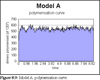
Once this change was made, the simulation was run again. This time the model created a very large number of very small fragments. Only once did a large microtubule begin to form - it reached a size of 84 dimers - however the average size was under 6, and most of the time all fragments were under 36 dimers in size. The simulation ran for 10 virtual seconds, but the microtubule size distribution did not change much after the first second.
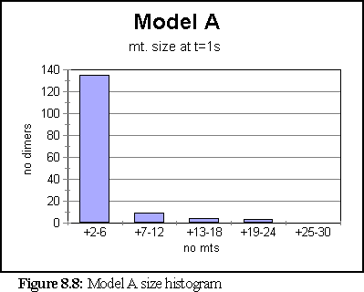
The polymerisation curve was likewise largely unchanged after 1s.
The state of the simulation at one second is shown in figure 8.10. It consists of a large number of small to medium sized fragments. The colour code (with alpha tubulin usually represented as slightly lighter than beta tubulin), used throughout this section, is :

This model represents a system where nucleation is too easy, and extended polymerisation too difficult. While many dimers can form the initial two or three dimer aggregates necessary to start building a microtubule, it is not possible for the microtubule to grow particularly large, since dimers break away too easily. Examination of the program trace logs indicates that the few larger aggregates that did form were largely the result of smaller aggregates combining, rather than accretion of dimers. At 15M concentration, a microtubule, once nucleated, should grow at around 100 dimers/second (Fig. 8.1) - obviously no aggregate did this, despite there being a number of reasonably large aggregates that might have displayed such behaviour had conditions been favourable.
The previous simulation failed to generate any large microtubules. One possible explanation for this is that the fragments are too friable, since the breakage chance is too large. In order to investigate this, the breakage probabilities were divided by two. This corresponds to a model of ragged microtubule tips where two dimers are held by a single bond.
The .pddf file is identical to Model A, except that (non-unity) breakage probabilities are divided by two,
p(bottom breakage) unstable GDP-tubulin = 0.018
p(side breakage) unstable GDP-tubulin = 0.018
p(bottom breakage) GTP-tubulin = 0.0011
p(side breakage) GTP-tubulin = 0.0011
p(top breakage) stable GDP-tubulin = 0.00055
p(bottom breakage) stable GDP-tubulin = 0.00055
p(side breakage) stable GDP-tubulin = 0.00055
The simulation was run for 6 simulated seconds. Again, no very large polymers were grown, although more material was polymerised and slightly larger nucleating fragments appeared. A measure of turnover can be obtained by noting that in six seconds over 18,000 aggregates were created and destroyed, implying that each dimer, on average, joined and broke apart from an aggregate 15 times.
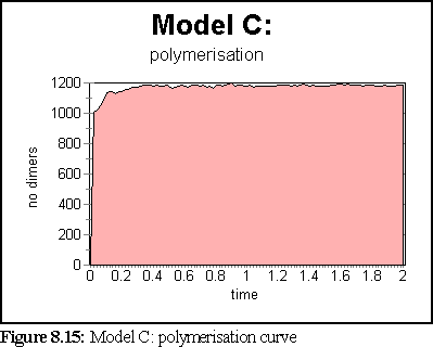
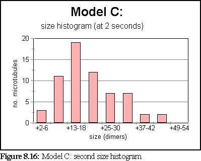
The simulation has attained steady state by the one second mark. At that stage, the size histogram is:
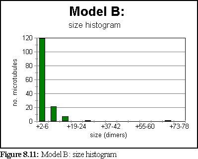
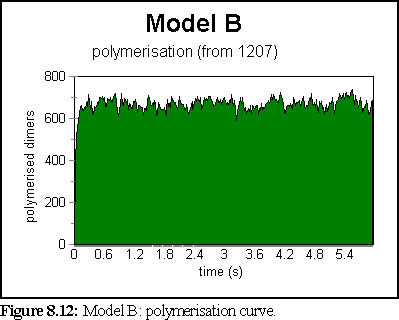
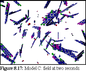
Figure 8.13 shows the simulation field at one second.

The second model suffered from the same problems as the first. Nucleation was too rapid, while microtubules were too unstable. Again, most large aggregates probably resulted from the merging of smaller aggregates, rather than gradual accretion. An interesting feature of both this and the previous model, is that the free dimers that were left represent a molarity of around 5-7M of free GTP-tubulin (since almost all free dimers are GTP-tubulin). This is refreshingly close to the theoretical value of 5M predicted for the steady state critical concentration, at which the amount of tubulin dimers accreting is the same as the amount breaking off (Fig. 8.1). The lower breakage figures did however give rise to slightly more, and slightly larger, nucleating fragments.
There is a possibility that underestimation of the binding probabilities is hindering microtubule growth. To test this hypothesis the binding probabilities of the Initial Estimate Model A are increased by a factor of 10:
p(top +) = .004
p(side) = .0007
p(bottom) = 0.0011
Note that this change presupposes an error in the original estimation of the number and type of collisions occurring at the tip of the microtubule. No such error is believed to have been made; this model is simply to test the possibility.
The solution rapidly degenerated into a large number of small to medium size fragments, possibly corresponding to a gel state. Since very few free GTP-tubulin dimers were available, the only growth path available was binding between aggregates, which did occur, and presumably would eventually have led to large microtubules, given sufficient time. However, in order to observe whether inter-aggregate binding was necessary, the simulation was run again without inter-aggregate binding being allowed, and a similar result (many small fragments) was obtained. The results reported here are from this second simulation.
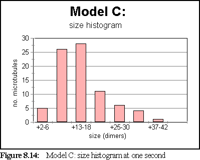
The polymerisation curve was very rapid, and peaked at a very high value (99.2% of starting dimers were polymerised at 0.9 seconds).
This does not represent the normal, dynamic microtubule growing environment corresponding to our base figures (since polymerisation has been very rapid), however it might well represent an abnormal environment that encouraged strong bonding.
Another possibility is that nucleation is too easy; that the initial bond between dimers should be lower, perhaps as a result of the greater mobility of the two binding objects, or some other effect such as the link being unnaturally weak without other dimers being present. In order to simulate this, the binding probabilities for un-attached dimers only are lowered by a factor of 100.
p(top +) = .000004
p(side) = .0000007
p(bottom) = 0.0000011
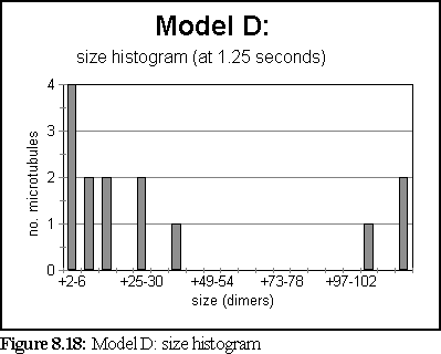
These probabilities provided a more realistic model of microtubule growth, corresponding more closely to what might be expected from the conditions outlined at the start of the chapter. The simulation was run for 1.25 virtual seconds, during which time less than half the free dimers were polymerised, but three large polymers formed, one of size greater than 140 dimers.
The polymerisation curve was also more consistent with experimental results:

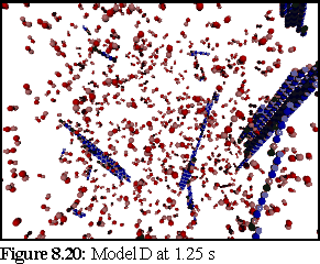
This is the most credible result so far. The creation of large, and still growing, polymers, combined with a realistic (albeit very rapid) polymerisation curve, gives credence to the notion that the initial nucleation probability is lower than that expressed by simply using the normal binding figures. This is probably a symptom of the simplicity of the binding model, which might be solved by moving to a more complete binding model based on energy considerations, where two bonds might be considerably stronger than 'ten times the strength of single bond', the ad-hoc heuristic currently used (cf Chapter 5).
To investigate the effect of increased breakage probabilities on model D, the breakage probabilities were increased by a factor of ten, corresponding to a model were dimers are all multiply bound at the tip (such as shown in Fig. 8.4).
The combination of low nucleation and high breakage resulted in a marked absence of polymers. During the (relatively fast) ten second run of the program, only one aggregate of size greater than 6 was created, and it survived for less than 20 milliseconds. The largest number of fragments present at one time was 5. No microtubules or aggregates of any reasonable size were ever created.
This leads to the conclusion that the breakage figures are at least approximately correct, and lends some support to the view that the growth tip of the microtubule is not the flat tip of figure 8.4, but a spiky tip such as in figure 8.5-8.6, or at least a ragged tip with more singly bound dimers.
Another model was investigated, this time using stronger side links. This led to a difficulty, that if the side links are made of equal strength to the top link, then the bottom link is forced to be a very low strength (due to equation 8.4). This led to the following figures being used:
p(top +) = .00013
p(side) = .00013
p(bottom) = .00001
In addition, the breakage probabilities were lowered by a factor of two, as in Model B, in order to further encourage assembly.
p(side) gdp - gdp(-s) = 0.018
p(bottom) gdp = 0.018
p(bottom) gtp - anything = 0.0011
p(side) gtp - anything = 0.0011
p(top/bottom) gdp-stable = 0.00055
p(side) gdp-s - gdp-s = 0.00055
The simulation ran for 5.3 seconds, at the end of which only 5 large aggregates existed, the smallest of which was 30-36 dimers in size, and the largest of which was over 220 dimers in size.
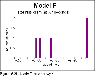

A third of a second earlier, at t=5s, there were 8 aggregates (rather than 5), as shown in figure 8.23.
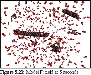
This is another result that appears plausible. It indicates that there can be a certain amount of flexibility in the balance between side and back/forward bonds without large scale polymerisation becoming impossible. This implies that a number of growth paths may be possible for microtubules under differing circumstances.
The highly variable polymerisation curve is curious. It may be due to the slightly smaller number of aggregates in the simulation, but it also seems possible that because these aggregates have more side growth (compare Fig. 8.20), they are somewhat more 'ragged', and are more inclined to rapid breakdown (possibly because they have more bound GTP-tubulin exposed). This in turn may be due to some subtle problems within the simulator, where binding events do not always seem to be correctly propagated to the neighbours of a newly bound dimer that 'slots into' a position with multiple bindings.
This simulation of various tubulin models shows that the nanoscale simulator is capable of modelling many of the characteristics of microtubule polymerisation during the initial growth phase. The simulator was able to track the initial growth phase of individual aggregates, and obtained statistics and information about the size distribution and polymerisation state of filaments during growth, as well as testing a variety of tubulin models.
Some tentative conclusions might be drawn from the preliminary results above. It appears that a modification to the initial tubulin model is required to prevent the rapid dephosphorelation of the pool of free GTP-tubulin through short-term assembly. The most likely mechanism is probably a time lag in the dephosphorylation of tubulin binding to the 'GTP cap'. The simulator results seems to support the possibility of short term links forming between dimers that do not immediately dephosphorylate them.
Two possible paths for growth are apparent. Either rapid and widespread nucleation, followed by merging of aggregates, or little nucleation, followed by growth from a steady addition of individual dimers. The simulator seems to support the latter as the more likely growth mode of large microtubules, however the initial effect (merging of polymers) may well be very important during nucleation to establish a stable nucleus.
There seems no reason at this stage to include large-scale effects explicitly in the model, as the simulator shows that microtubule construction can proceed adequately on the basis of local rules.
While there is some margin of error, there is a range of workable values for polymerisation. If breaking values are too great, no large aggregates form, while if binding values are too great, many small aggregates form. The simulator shows that values worked out from bulk properties are roughly correct, except that initial nucleation values are still debatable.
The simulator shows that a range of growth modes (stronger side links, or stronger axial links) appear geometrically possible.
The simulator supports the plausibility of the GTP-cap model, and shows that it can lead to microtubule creation. In addition, the simulator showed rapid disassembly of microtubules fragments that lost the stabilising cap.
The results in this chapter were obtained for relatively small numbers of dimers in a small volume, compared to the earlier actin results, due to limitations on computer time. However the experiments performed here show the utility of even such small scale simulations; larger simulation runs in the future should provide even stronger results, extending to features such as treadmilling and collapse/rescue. A larger simulation should also produce a smoother size histogram.
Index |
Last Chapter |
Next Chapter |
1. For further background see Amos, L.A. and Amos, B.A.(1991), Molecules of the Cytoskeleton, Macmillan, London, Chapter 7 pp 117-141
2. e.g. Gaskin, F., Cantor, C.R., and Shelanski, M.L. (1974), Turbidimetric Studies of the in-Vitro Assembly and Disassembly of Porcine Neurotubules, J. Mol. Biol., Vol 89, pp 737-758
3. Betts, C., 1997, Simulating Microtubule Assembly, Molecular Biophysics of the Cytoskeleton conference, Banff, Canada (hosted University of Alberta).
4. Image from ibid, p 134
5. Although somewhat controversial, especially in detail, this is the theory presented in textbooks such as Amos op.cit., and papers such as Bayley, P.M., Schilstra, M.J., and Martin, S.R., (1989) A lateral cap model for microtubule dynamic instability FEBS Lett. Vol 259, pp 181-184, and is used in existing models in papers such as Flyvbjerg, H., Holy, T.E., and Leibler, S., (1994), Stochastic Dynamics of Microtubules: A Model for Caps and Catastrophes, Phys. Rev. Lett. Vol 73, No. 17, pp 2372 - 2375
6. The cap theory is mathematically modeled in Flyvbjerg, H., Holy, T.E., and Leibler, S., (1996), Microtubule dynamics: Caps, catastrophes, and coupled hydrolysis, Phys Rev. E., Vol 54, No 5, pp 5538-5560
7. Jobs, E., Wolf, D.E., and Flyvbjerg, H., (1997), Modeling Microtubule Oscillations, Phys. Rev. Lett. Vol 29, No.3., pp 519-522
8. Amos & Amos, op.cit. p117-119
9. Note that this model, and the ones below, are static models for illustrative purposes, constructed using povray or other programming tools, and are not output from the simulator unless explicitly stated.
10. Oosawa, F. and Asakura, S. op. cit.
11. Fygenson, D.K. et al., (1995), Spontaneous nucleation of microtubules Phys. Rev. E., Vol 51, No. 5, pp 5058-5063
12. Voter, W. A. and Erickson, H.P. (1984), The Kinetics of Microtubule Assembly: Evidence for a Two-Stage Nucleation Mechanism, J. Bio. Chem., Vol 259, No 16, pp 10430-10438.
13. e.g. Flyvbjerg, H., Jobs, E. and Leibler, S. (1996), Kinetics of self-assembling microtubules: An "inverse problem" in biochemistry, Proc. Natl. Acad. Sci, Vol 93, pp5975-5979.
14. Tran, P.T., Joshi, P. and Salmon, E.D. (1997), How Tubulin Subunits are Lost from the Shortening Ends of Microtubules, J. Struct. Biol. Vol 118, pp 107-118, esp. p114.
15. Chrétien, D., Fuller, S.D. and Karsenti, E., (1995) Structure of Growing Micrtotubule Ends: Two-Dimensional Sheets Close Into Tubes at Variable Rates, J. Cell. Biol., Vol 129, No.5, pp 1311-1328
16. Chrétien, D., Flyvbjerg, H., Fuller, S.D., (1998) Limited flexibility of the inter-protofilament bonds in microtubules assembled from pure tubulin, Eur. Biophys. J., Vol 27, pp 490-500.
17. Jánosi, I.M., Chrétien, D. and Flyvbjerg, H., (1998) Modeling elastic properties of microtubule tips and walls, Eur. Biophys. J. Vol 27, pp 501-513.
18. Ibid.
19. Walker, R.A., O'Brien, E.T., Pryer, N.K., Soboeiro, M.R., Voter, W.A., Erickson, H.P. & Salmon, E.D. (1988), Dynamic instability of individual microtubules analyzed by video light microscopy: rate constants and transition frequencies., J. Cell Biol., Vol 103, pp 2747-2754
20. Ibid
21. Amos, L.A. and Amos, B.A.(1991), Molecules of the Cytoskeleton, Macmillan, London, Chapter 7 p 136
22. e.g. the various microtubule severing experiments, esp. Walker, R.A., Inoué, S., and Salmon, E.D. (1989), Asymmetric behaviour of severed microtubule ends after ultraviolet-microbeam irradiation of individual microtubules in vitro, J. Cell Biol, Vol 108, pp 931-37
23. cf review article Desai A. and Mitchison, J, (1997) Microtubule Polymerization Dynamics, Annu. Rev. Cell Dev. Biol., Vol 13 pp 83-117, esp sections "The GTP CAP Model" p95-97, "Structural Basis of Dynamic Instability"pp97-99 and "Relationship of Structural and Chemical Transitions" pp 99-100
24. Nogales, E., Whittaker, M., Milligan, R.A., and Downing, K.H., (1999) High Resolution Model of the Microtubule, Cell, Vol 96, pp 79-88
25. The model receives strong support from Nogales, E. ibid.
26. Amos, L.A. and Amos, B.A. op. cit. Chapter 7
27. Semënov, V. M., (1995) New Concept of Microtubule Dynamics and Microtubule Motor Movement and New Model of Chromosome Movement in Mitosis, J. theor. Biol., Vol 179 pp 91-117
28. A series of papers examining this issue has appeared from the lab of Peter M. Bayley, e.g. Martin, S.R., Schilstra, M.J. and Bayley, P.M. (1993) Dynamic Instability of Microtubules: Monte Carlo Simulation and Application to Different Types of Microtubule Lattice, Biophys. J. Vol 65, pp 578-596.